티스토리 뷰


https://surtrtech.com/2018/12/28/interfacing-1-heart-pulse-beat-sensor-amped-sen-11574-with-arduino/
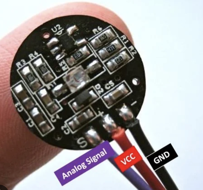
Interfacing 1$ Heart Pulse / Beat sensor AMPED SEN 11574 with Arduino
Hello, and welcome to this tutorial where we try to use a 1$ Heart pulse sensor, which obviously won’t be so accurate, the genuine on is made by “World Famous Elect…
surtrtech.com
Library:
Download AMPED SEN 11574 library from Github here or download from here.
pulsesensor

Codes:
The codes I’ve used are from the library: “Getting started” and “BPM” and are good for interfacing your module and understand how it works.
Unfortunately the module wasn’t working good to try BPM and other codes
Code 1: Library example – Getting started
/* PulseSensor Starter Project and Signal Tester
* The Best Way to Get Started With, or See the Raw Signal of, your PulseSensor.com™ & Arduino.
*
* Here is a link to the tutorial
* https://pulsesensor.com/pages/code-and-guide
*
* WATCH ME (Tutorial Video):
* https://www.youtube.com/watch?v=RbB8NSRa5X4
*
*
-------------------------------------------------------------
1) This shows a live human Heartbeat Pulse.
2) Live visualization in Arduino's Cool "Serial Plotter".
3) Blink an LED on each Heartbeat.
4) This is the direct Pulse Sensor's Signal.
5) A great first-step in troubleshooting your circuit and connections.
6) "Human-readable" code that is newbie friendly."

*/


// Variables
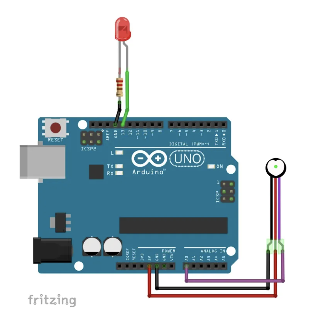
int PulseSensorPurplePin = 0; // Pulse Sensor PURPLE WIRE connected to ANALOG PIN 0
int LED = LED_BUILTIN; // The on-board Arduion LED


int Signal; // holds the incoming raw data. Signal value can range from 0-1024
int Threshold = 580; // Determine which Signal to "count as a beat", and which to ingore.


// The SetUp Function:
void setup() {
pinMode(LED,OUTPUT); // pin that will blink to your heartbeat!
Serial.begin(9600); // Set's up Serial Communication at certain speed.

}

// The Main Loop Function
void loop() {

Signal = analogRead(PulseSensorPurplePin); // Read the PulseSensor's value.
// Assign this value to the "Signal" variable.

Serial.println(Signal); // Send the Signal value to Serial Plotter.


if(Signal > Threshold){ // If the signal is above "550", then "turn-on" Arduino's on-Board LED.
digitalWrite(LED,HIGH);
} else {
digitalWrite(LED,LOW); // Else, the sigal must be below "550", so "turn-off" this LED.
}


delay(10);


}
Code 2: Library example – BPM measuring
/*
Code to detect pulses from the PulseSensor,
using an interrupt service routine.

Here is a link to the tutorial\
https://pulsesensor.com/pages/getting-advanced

Copyright World Famous Electronics LLC - see LICENSE
Contributors:
Joel Murphy, https://pulsesensor.com
Yury Gitman, https://pulsesensor.com
Bradford Needham, @bneedhamia, https://bluepapertech.com

Licensed under the MIT License, a copy of which
should have been included with this software.

This software is not intended for medical use.
*/

/*
Every Sketch that uses the PulseSensor Playground must
define USE_ARDUINO_INTERRUPTS before including PulseSensorPlayground.h.
Here, #define USE_ARDUINO_INTERRUPTS true tells the library to use
interrupts to automatically read and process PulseSensor data.

See PulseSensor_BPM_Alternative.ino for an example of not using interrupts.
*/
#define USE_ARDUINO_INTERRUPTS true
#include <PulseSensorPlayground.h>

/*
The format of our output.

Set this to PROCESSING_VISUALIZER if you're going to run
the Processing Visualizer Sketch.
See https://github.com/WorldFamousElectronics/PulseSensor_Amped_Processing_Visualizer

Set this to SERIAL_PLOTTER if you're going to run
the Arduino IDE's Serial Plotter.
*/
const int OUTPUT_TYPE = SERIAL_PLOTTER;

/*
Pinout:
PULSE_INPUT = Analog Input. Connected to the pulse sensor
purple (signal) wire.
PULSE_BLINK = digital Output. Connected to an LED (and 1K series resistor)
that will flash on each detected pulse.
PULSE_FADE = digital Output. PWM pin onnected to an LED (and 1K series resistor)
that will smoothly fade with each pulse.
NOTE: PULSE_FADE must be a pin that supports PWM. Do not use
pin 9 or 10, because those pins' PWM interferes with the sample timer.
THRESHOLD should be set higher than the PulseSensor signal idles
at when there is nothing touching it. The expected idle value
should be 512, which is 1/2 of the ADC range. To check the idle value
open a serial monitor and make note of the PulseSensor signal values
with nothing touching the sensor. THRESHOLD should be a value higher
than the range of idle noise by 25 to 50 or so. When the library
is finding heartbeats, the value is adjusted based on the pulse signal
waveform. THRESHOLD sets the default when there is no pulse present.
Adjust as neccesary.
*/
const int PULSE_INPUT = A0;
const int PULSE_BLINK = LED_BUILTIN;
const int PULSE_FADE = 5;
const int THRESHOLD = 550; // Adjust this number to avoid noise when idle

/*
All the PulseSensor Playground functions.
*/
PulseSensorPlayground pulseSensor;

void setup() {
/*
Use 115200 baud because that's what the Processing Sketch expects to read,
and because that speed provides about 11 bytes per millisecond.

If we used a slower baud rate, we'd likely write bytes faster than
they can be transmitted, which would mess up the timing
of readSensor() calls, which would make the pulse measurement
not work properly.
*/
Serial.begin(115200);

// Configure the PulseSensor manager.

pulseSensor.analogInput(PULSE_INPUT);
pulseSensor.blinkOnPulse(PULSE_BLINK);
pulseSensor.fadeOnPulse(PULSE_FADE);

pulseSensor.setSerial(Serial);
pulseSensor.setOutputType(OUTPUT_TYPE);
pulseSensor.setThreshold(THRESHOLD);

// Now that everything is ready, start reading the PulseSensor signal.
if (!pulseSensor.begin()) {
/*
PulseSensor initialization failed,
likely because our particular Arduino platform interrupts
aren't supported yet.

If your Sketch hangs here, try PulseSensor_BPM_Alternative.ino,
which doesn't use interrupts.
*/
for(;;) {
// Flash the led to show things didn't work.
digitalWrite(PULSE_BLINK, LOW);
delay(50); Serial.println('!');
digitalWrite(PULSE_BLINK, HIGH);
delay(50);
}
}
}

void loop() {
/*
Wait a bit.
We don't output every sample, because our baud rate
won't support that much I/O.
*/
delay(20);

// write the latest sample to Serial.
pulseSensor.outputSample();

/*
If a beat has happened since we last checked,
write the per-beat information to Serial.
*/
if (pulseSensor.sawStartOfBeat()) {
pulseSensor.outputBeat();
}
}
Code 3:
And here’s the code I’ve used with the Buzzer, they have another one in examples, but I modified mine, don’t forget to watch the tutorial video in case you want to know why it’s difficult to measure my heart beat by this dodgy version.
/* PulseSensor Starter Project and Signal Tester
* The Best Way to Get Started With, or See the Raw Signal of, your PulseSensor.com™ & Arduino.
*
* Here is a link to the tutorial
* https://pulsesensor.com/pages/code-and-guide
*
* WATCH ME (Tutorial Video):
* https://www.youtube.com/watch?v=RbB8NSRa5X4
*
*
-------------------------------------------------------------
1) This shows a live human Heartbeat Pulse.
2) Live visualization in Arduino's Cool "Serial Plotter".
3) Blink an LED on each Heartbeat.
4) This is the direct Pulse Sensor's Signal.
5) A great first-step in troubleshooting your circuit and connections.
6) "Human-readable" code that is newbie friendly."
*/
//Code modified by www.surtrtech.com to work with a buzzer
// Variables
int PulseSensorPurplePin = 0; // Pulse Sensor PURPLE WIRE connected to ANALOG PIN 0
int LED13 = 13; // The on-board Arduion LED
int Buzzer=12;
int Signal; // holds the incoming raw data. Signal value can range from 0-1024
int Threshold = 519 ; // Determine which Signal to "count as a beat", and which to ingore.
// The SetUp Function:
void setup() {
pinMode(Buzzer,OUTPUT);
pinMode(LED13,OUTPUT); // pin that will blink to your heartbeat!
Serial.begin(9600); // Set's up Serial Communication at certain speed.
}
// The Main Loop Function
void loop() {
Signal = analogRead(PulseSensorPurplePin); // Read the PulseSensor's value.
// Assign this value to the "Signal" variable.
Serial.println(Signal); // Send the Signal value to Serial Plotter.
if(Signal > Threshold ){ // If the signal is above "519", then "turn-on" Arduino's on-Board LED.
digitalWrite(LED13,HIGH);
tone(Buzzer,1000);
delay(100);
} else {
digitalWrite(LED13,LOW); // Else, the sigal must be below "519", so "turn-off" this LED.
noTone(Buzzer);
}
delay(10);
}
'Iot > Arduino' 카테고리의 다른 글
| VL53L1X ToF 레이저 거리 측정 센서 모듈_아두이노 (0) | 2024.01.09 |
|---|---|
| RedBoard Sparkfun _아두이노 오류 _ 보드 설치 (0) | 2024.01.09 |
| 아두이노 _ MLX90614 _ 비접촉 온도센서 (0) | 2024.01.08 |
| 아두이노 + GSR sensor + 서보모터 (0) | 2023.05.25 |
| Unity2021.3.11_win_Arduino (0) | 2023.05.11 |
- Total
- Today
- Yesterday
- TouchDesigner
- MQTT
- MCP
- colab
- opencv
- DeepLeaning
- node.js
- Unity
- Arduino
- AI
- RNN
- 유니티
- Midjourney
- CNC
- 4d guassian splatting
- 4dgs
- docker
- 후디니
- Express
- houdini
- Java
- Python
- sequelize
- 라즈베리파이
- VR
- ai film
- three.js
- VFXgraph
- krea
- opticalflow
| 일 | 월 | 화 | 수 | 목 | 금 | 토 |
|---|---|---|---|---|---|---|
| 1 | 2 | 3 | 4 | 5 | 6 | 7 |
| 8 | 9 | 10 | 11 | 12 | 13 | 14 |
| 15 | 16 | 17 | 18 | 19 | 20 | 21 |
| 22 | 23 | 24 | 25 | 26 | 27 | 28 |
