티스토리 뷰


https://blog.naver.com/chansystem/221751370878
#. Arduino UNO :: OV7670 (VGA 카메라 모듈)
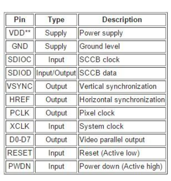
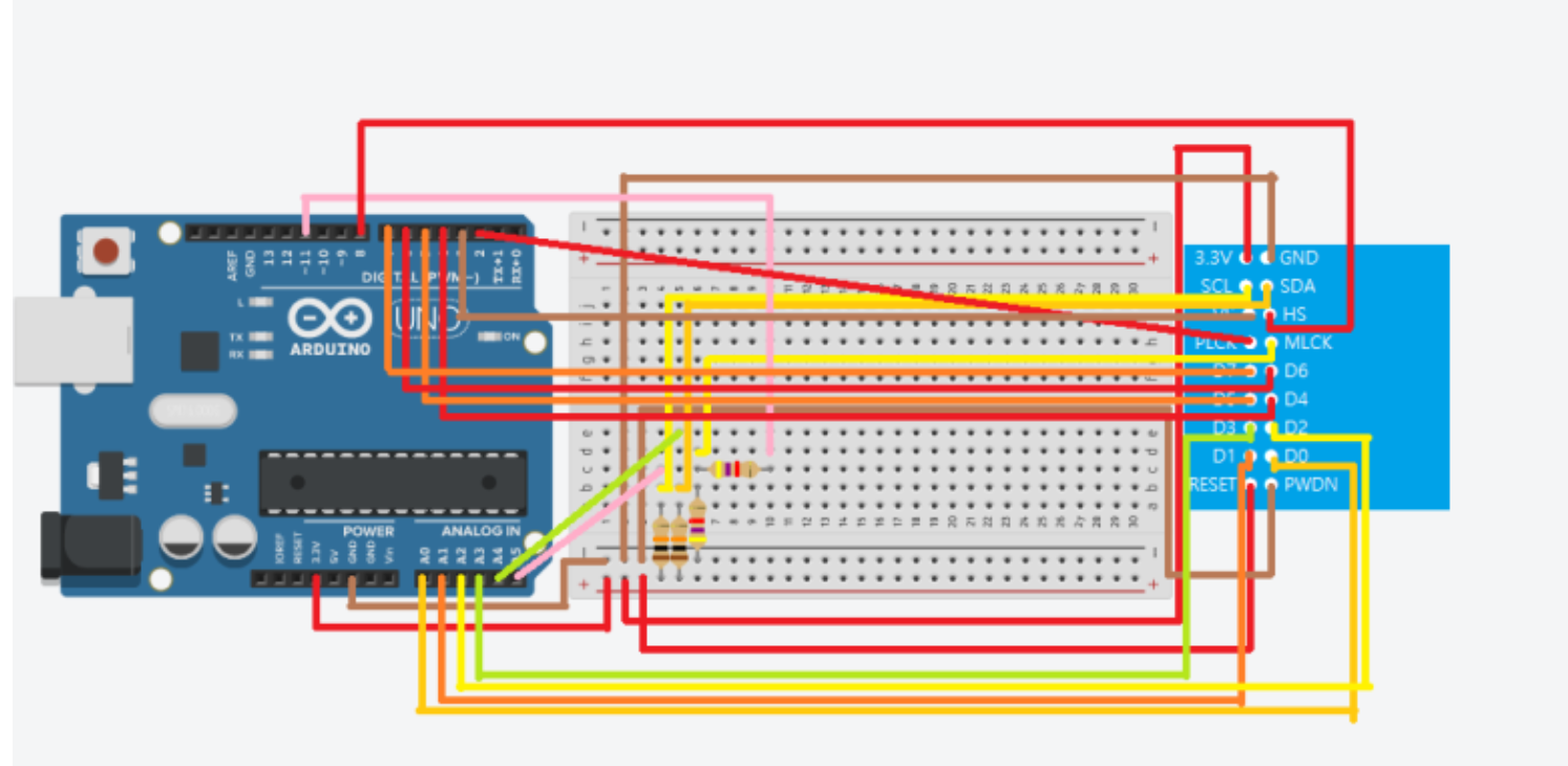
Arduino UNO와 OV7670을 연결하여 PC에서 Camera 이미지를 출력하는 방법에 대한 것이다. 회로와 ...
blog.naver.com


https://forum.arduino.cc/t/pro
blem-in-connection-between-arduino-mega-and-ov7670/523637
PROBLEM in connection between Arduino Mega and ov7670
i wanna to do connect between Arduino Mega 2560 and ov7670 i try this connection with this code but when i try to run it stop there without and output
forum.arduino.cc


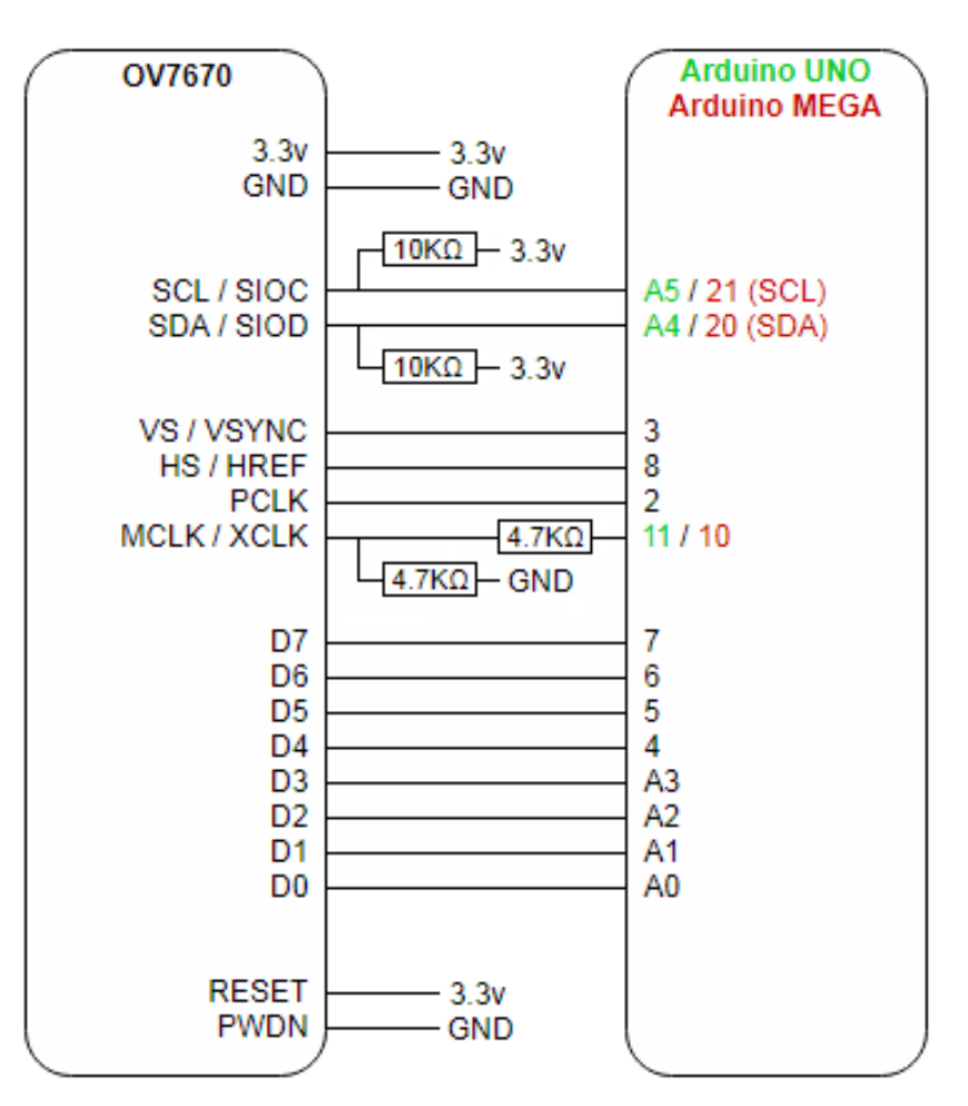
// Pins configurations:
// SDA/SIOD ---> pin A4 (for Arduino UNO) | pin 20/SDA (for Arduino MEGA)
// SCL/SIOC ---> pin A5 (for Arduino UNO) | pin 21/SCL (for Arduino MEGA)
// MCLK/XCLK --> pin 11 (for Arduino UNO) | pin 10 (for Arduino MEGA)
// PCLK -------> pin 2
// VS/VSYNC ---> pin 3
// HS/HREF ----> pin 8
// D0 ---------> pin A0
// D1 ---------> pin A1
// D2 ---------> pin A2
// D3 ---------> pin A3
// D4 ---------> pin 4
// D5 ---------> pin 5
// D6 ---------> pin 6
// D7 ---------> pin 7

#include <Wire.h>

#define CAMERA_ADDRESS 0x21

// Definitions of functions for manipulating the Arduino boards pins according to each Arduino board registers, so the code will work for both Arduino UNO and Arduino MEGA:
// The only change is the connections of the SDA/SIOD, SCL/SIOC and MCLK/XCLK pins to each board (see the pins configurations above).
#if defined(__AVR_ATmega1280__) || defined(__AVR_ATmega2560__) // If you are using Arduino MEGA the IDE will automatically define the "__AVR_ATmega1280__" or "__AVR_ATmega2560__" constants.
#define TIMER2_PWM_A_PIN_MODE_OUTPUT() ({ DDRB |= 0b00010000; })
#define PIN2_DIGITAL_READ() ({ (PINE & 0b00010000) == 0 ? LOW : HIGH; })
#define PIN3_DIGITAL_READ() ({ (PINE & 0b00100000) == 0 ? LOW : HIGH; })
#define PIN4_DIGITAL_READ() ({ (PING & 0b00100000) == 0 ? LOW : HIGH; })
#define PIN5_DIGITAL_READ() ({ (PINE & 0b00001000) == 0 ? LOW : HIGH; })
#define PIN6_DIGITAL_READ() ({ (PINH & 0b00001000) == 0 ? LOW : HIGH; })
#define PIN7_DIGITAL_READ() ({ (PINH & 0b00010000) == 0 ? LOW : HIGH; })
#define PIN8_DIGITAL_READ() ({ (PINH & 0b00100000) == 0 ? LOW : HIGH; })
#define PINA0_DIGITAL_READ() ({ (PINF & 0b00000001) == 0 ? LOW : HIGH; })
#define PINA1_DIGITAL_READ() ({ (PINF & 0b00000010) == 0 ? LOW : HIGH; })
#define PINA2_DIGITAL_READ() ({ (PINF & 0b00000100) == 0 ? LOW : HIGH; })
#define PINA3_DIGITAL_READ() ({ (PINF & 0b00001000) == 0 ? LOW : HIGH; })
#elif defined(__AVR_ATmega328P__) // If you are using Arduino UNO the IDE will automatically define the "__AVR_ATmega328P__" constant.
#define TIMER2_PWM_A_PIN_MODE_OUTPUT() ({ DDRB |= 0b00001000; })
#define PIN2_DIGITAL_READ() ({ (PIND & 0b00000100) == 0 ? LOW : HIGH; })
#define PIN3_DIGITAL_READ() ({ (PIND & 0b00001000) == 0 ? LOW : HIGH; })
#define PIN4_DIGITAL_READ() ({ (PIND & 0b00010000) == 0 ? LOW : HIGH; })
#define PIN5_DIGITAL_READ() ({ (PIND & 0b00100000) == 0 ? LOW : HIGH; })
#define PIN6_DIGITAL_READ() ({ (PIND & 0b01000000) == 0 ? LOW : HIGH; })
#define PIN7_DIGITAL_READ() ({ (PIND & 0b10000000) == 0 ? LOW : HIGH; })
#define PIN8_DIGITAL_READ() ({ (PINB & 0b00000001) == 0 ? LOW : HIGH; })
#define PINA0_DIGITAL_READ() ({ (PINC & 0b00000001) == 0 ? LOW : HIGH; })
#define PINA1_DIGITAL_READ() ({ (PINC & 0b00000010) == 0 ? LOW : HIGH; })
#define PINA2_DIGITAL_READ() ({ (PINC & 0b00000100) == 0 ? LOW : HIGH; })
#define PINA3_DIGITAL_READ() ({ (PINC & 0b00001000) == 0 ? LOW : HIGH; })
#endif


void initializePWMTimer() {
  cli();
  TIMER2_PWM_A_PIN_MODE_OUTPUT(); // Set the A PWM pin of TIMER2 to output
  ASSR &= ~(_BV(EXCLK) | _BV(AS2));
  TCCR2A = (1 << COM2A0) | (1 << WGM21) | (1 << WGM20);
  TCCR2B = (1 << WGM22) | (1 << CS20);
  OCR2A = 0;
  sei();
}

byte readCameraRegister(byte registerId) {
  Wire.beginTransmission(CAMERA_ADDRESS);
  Wire.write(registerId);
  Wire.endTransmission();
  Wire.requestFrom(CAMERA_ADDRESS, 1);
  while (Wire.available() <= 0);
  byte registerValue = Wire.read();
  delay(1);
  return registerValue;
}

void writeCameraRegister(byte registerId, byte registerValue) {
  Wire.beginTransmission(CAMERA_ADDRESS);
  Wire.write(registerId);
  Wire.write(registerValue);
  Wire.endTransmission();
  delay(1);
}

void captureFrame(unsigned int frameWidth, unsigned int frameHeight) {
  Serial.print("*RDY*"); // send to the frame capture software a "start of frame" message for beginning capturing

  delay(1000);

  cli(); // disable all interrupts during frame capture (because it needs to be as fast as possible)
  while (PIN3_DIGITAL_READ() == LOW); // wait until VS/VSYNC pin is high
  while (PIN3_DIGITAL_READ() == HIGH); // wait until VS/VSYNC pin is low
  unsigned int tempWidth = 0;
  while (frameHeight--) {
    tempWidth = frameWidth;
    while (tempWidth--) {
      while (PIN2_DIGITAL_READ() == LOW); // wait until PCLK pin is high
      while (PIN2_DIGITAL_READ() == HIGH); // wait until PCLK pin is low
      byte byteToWrite = 0b00000000;
      byteToWrite |= ((PIN7_DIGITAL_READ() == HIGH) << 7);
      byteToWrite |= ((PIN6_DIGITAL_READ() == HIGH) << 6);
      byteToWrite |= ((PIN5_DIGITAL_READ() == HIGH) << 5);
      byteToWrite |= ((PIN4_DIGITAL_READ() == HIGH) << 4);
      byteToWrite |= ((PINA3_DIGITAL_READ() == HIGH) << 3);
      byteToWrite |= ((PINA2_DIGITAL_READ() == HIGH) << 2);
      byteToWrite |= ((PINA1_DIGITAL_READ() == HIGH) << 1);
      byteToWrite |= ((PINA0_DIGITAL_READ() == HIGH));
      UDR0 = byteToWrite; // send data via serial connection with UART register (we need to use the serial register directly for fast transfer)
      while (PIN2_DIGITAL_READ() == LOW); // wait until PCLK pin is high
      while (PIN2_DIGITAL_READ() == HIGH); // wait until PCLK pin is low
      // ignore each second byte (for a grayscale image we only need each first byte, which represents luminescence)
    }
  }
  sei(); // enable all interrupts

  delay(1000);
}


void setup() {
  initializePWMTimer();
  Wire.begin();
  Serial.begin(1000000); // the frame capture software communicates with the Arduino at a baud rate of 1MHz
}

void loop() {
  captureFrame(320, 240); // capture a frame at QVGA resolution (320 x 240)
}
이미지 받아오기
https://circuitdigest.com/microcontroller-projects/how-to-use-ov7670-camera-module-with-arduino
How to Use OV7670 Camera Module with Arduino
Cameras have always dominated the electronics industry as it has lots of applications such as visitor monitoring system, surveillance system, attendance system etc. Cameras that we use today are smart and have a lot of features that were not present in ear
circuitdigest.com
https://electricdiylab.com/how-to-use-ov7670-camera-module-with-arduino-taking-live-pictures/
How to use OV7670 Camera module with arduino taking live pictures - Electric DIY Lab
Hello friends in this post we will learn how simply we can connect OV7670 Camera module with arduino and taking and saving live pictures.
electricdiylab.com
'Iot > Arduino' 카테고리의 다른 글
| arduino nano 33 IoT _ 무선 wifi 연결 + mqtt 통신 (0) | 2024.04.15 |
|---|---|
| 미니모터(ja12-n20) +아두이노 + 드라이버 (HG7881) (0) | 2024.03.30 |
| 아두이노 + LED strip (6812 RGBW) (0) | 2024.02.21 |
| 아두이노+LM386 디지털 앰프 모듈+스피커 ELB060302_*오디오파일 바이트 코드로 바꾸기 (0) | 2024.02.21 |
| 아두이노에 여러개의 센서 연결하기 (DS18B20 온도센서) (0) | 2024.02.21 |
- Total
- Today
- Yesterday
- Midjourney
- krea
- opencv
- Python
- colab
- docker
- 후디니
- Java
- Arduino
- 유니티
- 4dgs
- opticalflow
- AI
- ai film
- VFXgraph
- houdini
- TouchDesigner
- CNC
- node.js
- Express
- RNN
- DeepLeaning
- three.js
- MQTT
- sequelize
- VR
- MCP
- 4d guassian splatting
- 라즈베리파이
- Unity
| 일 | 월 | 화 | 수 | 목 | 금 | 토 |
|---|---|---|---|---|---|---|
| 1 | 2 | 3 | 4 | 5 | 6 | 7 |
| 8 | 9 | 10 | 11 | 12 | 13 | 14 |
| 15 | 16 | 17 | 18 | 19 | 20 | 21 |
| 22 | 23 | 24 | 25 | 26 | 27 | 28 |
